ENGINE MANAGEMENT ECU
FAQ : AUTRONIC ECU CLEAR PASSWORD PROCEDURE
While an ECU is password protected, it cannot be adjusted and its calibration cannot be recovered.
Back-up copies of its calibration and the chosen password should therefore be made prior to password protecting an ECU.
If the password is unknown, further adjustment or replacement of the ECU calibration is not possible.
If calibration change or replacement is required and the password is unknown, the only method available to unlock the ECU is the Clear Password procedure. The Clear Password procedure will destroy the calibration and the password contained within the ECU. Engine/vehicle operation will not be possible until an ECU configuration / calibration is installed that suits the application.
If you do not have a backup copy of the existing ECU calibration you will need to reconfigure the ECU and develop a new calibration to match the ECU to the application. To do this you will need full knowledge of the hardware that the ECU is connected to in order to undertake configuration and calibration development. The information required includes details of all wiring, injection and ignition systems, variable cam, other actuators (e.g. Fuel pump/s, Fan/s, Idle motors, boost control solenoid/s), digital inputs (e.g. crankshaft and/or camshaft triggers, speed and switch Inputs) and analogue inputs (e.g. manifold absolute pressure, throttle position, air and coolant temperature inputs.)
Warning
The Clear Password procedure will cause total loss of all ECU setup. All application specific setup and engine calibration will be lost. Vehicle operation will not be possible until the ECU is configured and calibrated to suit the application.
ECU outputs will assume an undefined state from the commencement of the clear password process until the ECU is suitably reconfigured. This can damage the ECU, injectors, ignition coils, ignition modules, actuators and electrical wiring. The engine cylinders could be filled with fuel and a fuel or electrical fire could occur. In order to protect against such dangers ALL INJECTORS, FUEL PUMPS, IGNITION COILS, IGNITION modules AND ACTUATORS MUST BE de-powered until the ECU is fully reconfigured. De-powering should preferably be done by disconnection of all injectors, ignition coils, ignition modules and actuators controlled by the ECU.
In all cases the calibration cannot be recovered from an ECU if the password is unknown. In some instances it may be possible to recover a calibration file from the ORIGINAL PC that was used to perform the ECU calibration, provided the PC has not had its Hard Disk Drive (HDD) changed or its HDD has not been reformatted since the calibration was performed
FAQ : Dealing with ECU CMOS errors
Autronic ECUs contain CMOS random access memory (RAM) for storage of error history, internal Data Logger set-up configuration, internal Data Logger data, and many adaptive variables including Throttle Position Sensor limit, closed loop lambda control, closed loop idle speed control, and cold start history. This CMOS RAM’s complete memory content is lost if its electrical supply is not sustained. Electrical supply is maintained during normal engine operation by the ignition supply; during ignition off periods by a +12 volt permanent supply connection to the ECU; and during periods of complete power disruption or while removed from the vehicle by a super capacitor within the ECU. The super capacitor is normally able to maintain supply to the CMOS RAM for more than one week, usually several months, depending upon the age of the ECU and its storage temperature after power supply disconnection.
Once the super cap is discharged, all CMOS RAM data including adaptive variables and ECU internal data logger set-up are lost, and a CMOS error is logged. Engine operation following this loss will be temporarily disturbed. Throttle response, idle speed control, boost control, closed loop mixture control, cold start-up and running, and other functions may be affected until the ECU fully re-adapts to the engine. Throttle response can be restored immediately by performing a throttle limit learning procedure (see: How do I calibrate the Throttle Position Sensor?).
CMOS memory loss will be present in all ECUs that have been stored disconnected from a 12v power source for an extended period (typically occurs within 3 months of disconnection from power source). It is normal behaviour for new ECUs that have been stored prior to installation.
CMOS memory loss can be prevented by maintaining power supply to the ECU +12 volt RAM supply connection.
This memory loss predominantly occurs in race car installations that have +12 volt RAM supply connection interrupted by a battery isolator switch (Kill Switch).
It should be noted that since the +12 volt RAM supply connection current draw is typically only several mA and its contribution to vehicle battery self-discharge is negligible, permanent connection to the vehicle battery (via suitable protective fuse or circuit breaker) is always recommended.
CMOS memory loss that occurs while correctly connected permanently maintained power supply source (> 6.0 volts DC) is indicative of an ECU fault condition. It should be returned to Autronic for repair.
After a CMOS memory loss, use the PC calibration software to reconfigure the ECU internal data logger and clear the logged CMOS loss error. Under the software Menu ‘M0’ select the ‘ERROR HISTORY’ screen, hit ‘r’ key to clear the CMOS loss error. This procedure does not function if the CMOS error display value is ‘NOW’. Cycling the Ignition power OFF then ON should change the CMOS error history display value to ‘RECENT’. In the ‘RECENT’ state clearing is possible. If the Ignition power OFF then ON cycling does not change the value to ‘RECENT’ the ECU is faulty. Return it to Autronic for repair.
FAQ: THROTTLE POSITION LIMIT CALIBRATION
AUTOMATIC / ADAPTIVE LIMIT LEARNING
All Autronic ECUs are equipped with an automatic adaptive learning function that simplifies the procedure for throttle position sensor calibration.
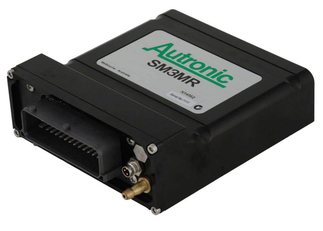
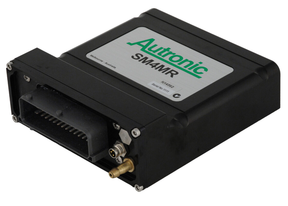
SM3 and SM4 ECUs, and derivatives with firmware revisions from v1.08, require that this mode be activated and set-up using the PC calibration program. All other ECUs use this mode exclusively and do not require any initial set-up using the laptop calibration program.
The adaptive limit learning function of all ECU models is compatible with throttle / sensor assemblies that meet the following specifications:
- a. The fully closed throttle sensor output voltage must be in the range 0.4 to 1.8 volts.
- b. The fully open throttle sensor output voltage must be in the range 3.2 to 4.7 volts.
- c. The difference between the voltages at the extremes of travel should be greater than 2.5 volts.
- d. The sensor output voltage must increase smoothly with increasing throttle opening, and there should be no dead spots in the total range of throttle travel.
(SM3 and SM4 ECUs, and derivatives with firmware revisions from v1.08 require user selection of error detection thresholds and have less restrictive voltage requirements. See the relevant calibration software TPS setup screen for applicable limits).
The adaptive learning initialization procedure is as follows:
- Ignition switch on, engine stopped.
- Disconnect throttle position electrical connector for at least 5 seconds.
- Reconnect throttle position electrical connector.
- Ensure that the throttle remains fully closed for at least 5 seconds. 5. Fully open the throttle for at least 5 seconds.
New limits of throttle travel will have been learnt and stored in the ECU during the above procedure. Additional ECU functions ensure that throttle stops and sensor wear are compensated for over the life of the engine. The above adaptive learning initialization procedure need only be repeated if the throttle travel stops are adjusted to reduce the range of throttle travel, or if the throttle / sensor assembly is serviced or replaced.
MANUAL / FIXED LIMIT SETTING
SM3 and SM4 ECUs and derivatives with firmware revisions from v1.08, also have a non-adaptive fixed throttle position limit setting mode. This mode requires the use of the PC calibration software for activation, and setting limits of travel and error detection thresholds. This is the non-preferred method, and should only be used in applications where throttle travel limits are affected by temperature, boost pressure or are inconsistent because of poor mechanical construction. Fixed limit mode MUST NOT be used in road car applications where either emissions control or idle speed control are utilized. See the relevant calibration software TPS setup screen for applicable limits.
IMPORTANT
Do not forget to use the PC calibration software to set-up the ‘Limp Home TPS’ and ‘Limp Home Manifold’ tables. In most applications, when correctly set these tables allow safe and almost normal engine operation during Throttle position and/or Manifold Absolute Pressure sensor failure.
FAQ: PROBLEMS WITH FLYING MAGNET TRIGGERS
Autronic Reluctor Interface Modules and Autronic ECUs equipped with reluctor interface functionality, are not designed to work with multi-pulse flying magnet trigger wheels. Such trigger wheels mis-trigger at high RPM if all the magnets are not precisely matched for magnetic flux strength. Experience has shown that after market trigger wheels of this type have not been sufficiently well matched to work reliably with our reluctor interfaces. Uniformly machined mild steel trigger wheels operating with a matching magnet equipped reluctor sensor, are the preferred choice for reliable triggering. This is also the method most commonly adopted for OEM triggering.
We only recommend using flying magnet triggers for single pulse per wheel rev applications (eg: Camshaft reference pick-up), since no matching is required for a single magnet.
FAQ: SMC ECU / WIRING LOOM COMPATIBILITY
SMC ECUs have been supplied with two external connection variations.The looms supplied with late revision ECUs are compatible with ALL SMC ECUs.The looms supplied with early revision ECUs are only compatible with early SMC ECUs. Use of a late revision SMC ECU with an early loom will prevent reliable ECU to PC data link operation, however damage will not occur to either the ECU or PC.
Early looms can be converted to late revision specification by moving the Serial data link ground connection (black wire) contact terminal from Pin 21 position to Pin 34 position. If a switch I/P connection is required (available on late SMC ECUs only), insert a wire with attached contact terminal and seal into the vacant Pin 21 position. Refer to SMC standard loom.
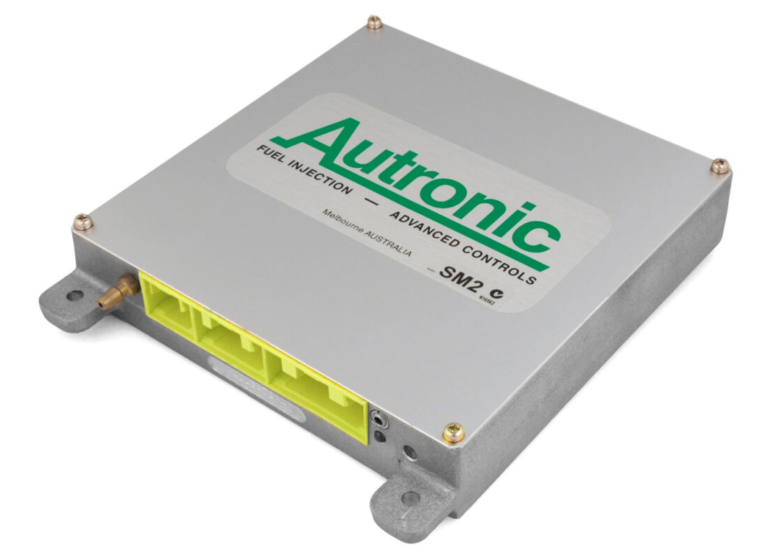
FAQ: SM2, SMC & SMC FAMILY PLUG-IN ECU INJECTOR COMPATIBILITY
Accurate delivery of fuel requires both correct electrical drive and precise compensation for the electro-mechanical properties of the injector (dead time correction). Correct injector operation, avoidance of injector and/or engine damage requires that both the dead time calibration and the driver characteristic match the engine’s injectors.
The SMC, SMC Marine, Mitsubishi EVO IV to VIII, Subaru WRX-STI 1999-2000 and SM2 ECUs do not have programmable injector output current drive selection. Therefore the PC software injector calibration screen is only able to perform injector dead time correction selection. The actual injector drive current characteristic is determined by the installed driver type and/or an internal PCB jumper selection.
The OEM installation in some vehicles (e.g. Mitsubishi EVO) will have ballast resistors connected in series with the injectors. When fitting non OEM injectors these resistors may need to be removed. Refer to the PC software injector characteristic selection screen for ballast resistor requirements relevant to the injector type. If the injector selection list does not include a setting with ballast resistor, remove the resistors.
When making the injector type selection using the PC software, ensure that the ECU’s output current drive characteristic matches the software recommended drive requirement.
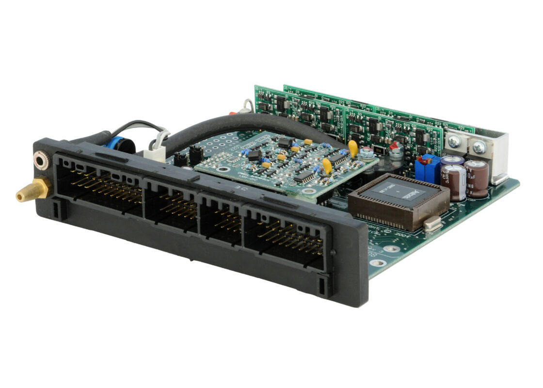
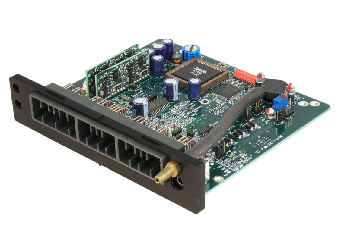
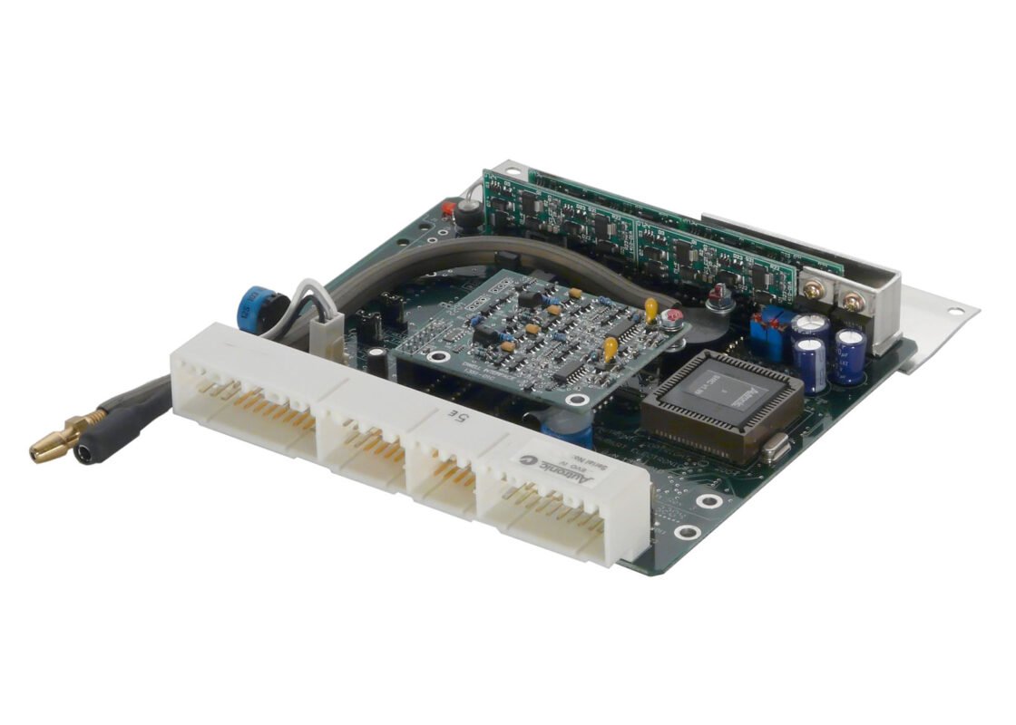
IDENTIFYING THE ECU INJECTOR DRIVE CURRENT CHARACTERISTIC
SMC & SM2 ECU serial number coding allows identification of injector drive characteristic. ECUs with serial numbers ending in ‘A2’ provide 2/0.5 Amp peak and hold drive. Serial numbers ending with ‘A4″ deliver 4/1 Amp peak and hold drive. Early revision ECUs are equipped with fixed current injector driver ICs that are attached to the ECU’s case. All later revision PCBs have configurable injector driver modules. See the table below for details.
Injector drive characteristics of the plug-in ECUs (Mitsubishi EVO IV to VIII & Subaru WRX/STI 1999 – 2000) cannot be determined from serial number coding. These ECUs usually are shipped with driver characteristics to match the OEM injectors of the intended vehicle model (usually 2/0.5 Amp). Early revision ECUs have fixed current injector driver ICs that are attached to an aluminium heat sink. Low current driver ICs (2/0.5 Amp) are inscribed with part numbers MC3484S2-1 or CS452, whereas high current driver ICs (4/1 Amp) have part numbers MC3484S4-2 or CS453. All later revision PCBs have configurable injector driver modules. See the table below for details.
| CHANGING THE ECU INJECTOR DRIVE CURRENT | |||
| ECU | Jumpering for low Current (2/0.5 Amp peak/hold) |
Jumpering for High Current (4/1 Amp peak/hold) |
|
| SMC (rev A, B & C PCBs to S/N: L5386) |
Non-configurable injector drivers ICs ¹ | ||
| SM2 (rev A, B, C, D & E PBCs to S/N: L2025) |
Non-configurable injector drivers ICs ¹ | ||
| Plug-in ECUs for Mitsubishi EVO IV to VIII & Subaru WRX-STI 1999 – 2000 (rev A & B PCBs B/N 1350-01 A & B) | Non-configurable injector drivers ICs ¹ | ||
| SMC (rev D & E PCBs from S/N: L5387) |
JP2 link pins 1-2 | JP2 link pins 2-3 | See Jumper location |
| SM2 (rev F & G PBCs from S/N: L2026) |
CON3 link pins 1-2 | CON3 link pins 2-3 | See Jumper location |
| Plug-in ECUs for Mitsubishi EVO IV to VIII & Subaru WRX-STI 1999 – 2000 (rev C & D PCBs B/N 1350-01 C & D) | JP2 link pins 1-2 | JP2 open circuit pins 1-2 | See Jumper location |
Notes:
ECUs equipped with non-configurable driver ICs can only have their drive current changed by replacing the driver ICs. The AUTRONIC service centre has limited quantities of these now obsolete drivers. We can provide a service to change drivers to suit your injectors, subject to driver availability.
FAQ : SERIAL COMMUNICATION LINK SETUP & FAULT DIAGNOSIS
For Autronic ECUs equipped with a RS232 Serial communication port, a serial communication port equipped PC running Autronic PC software is required for calibration, diagnosis and data retrieval. Reliable communication is only possible when the software is directed to use a correctly configured serial communication port and this communication port is correctly connected to the ECU serial port. The PC serial communication port can be a built-in type (when available) or added to the PC by installing a USB to Serial adaptor (see note 1).
If the Autronic PC software fails to automatically establish communications with your Autronic ECU, the following procedure should resolve the problem (also see note 2).
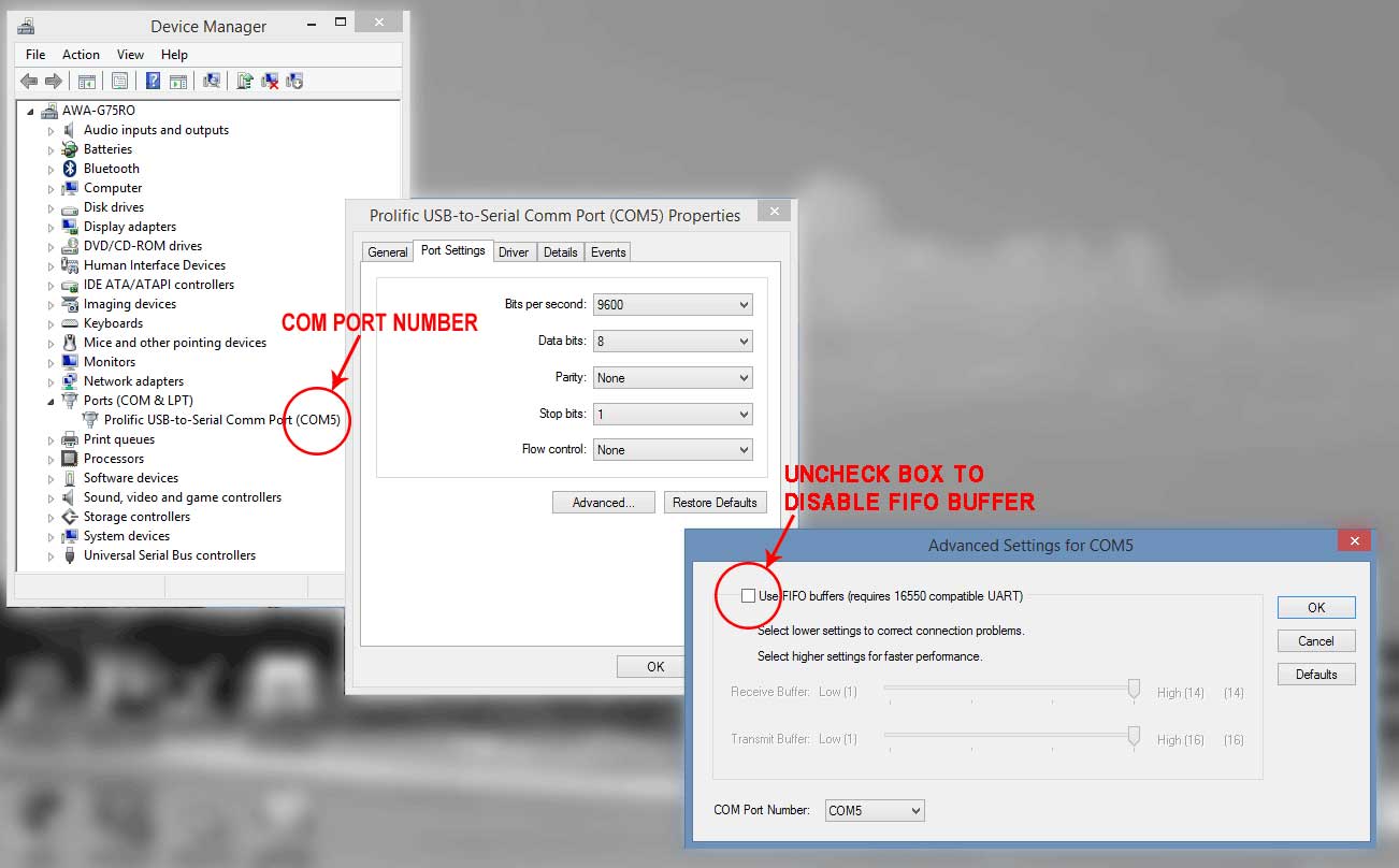
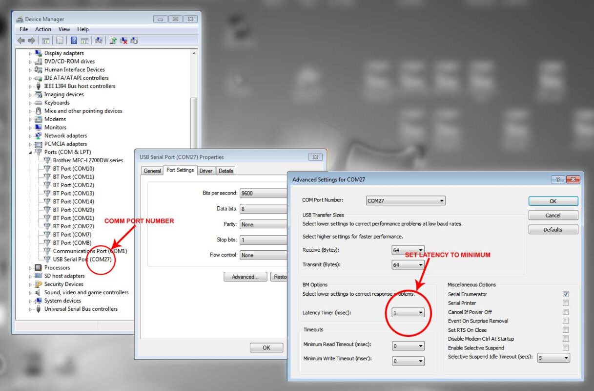
1. DETERMINE THE COMMUNICATION PORT NUMBER
Use the computers “Device Manager” screen to confirm the presence of an installed Serial communication port. More than one communication port may be available. Note the number of the port that you intend to use, so that the Autronic software can be set accordingly. The example shows one available com port, COM5.
(For SMC/SM2 ECU family software, only communication port numbers below 11 are supported. If the com port number is outside this allowed range, click on the chosen port to open its port properties screen. Select the “Port Settings” tab, then click on the ”advanced” button. In the “Advanced Settings” window, select an unused com port number less than 11.)
2. CONFIGURE THE COMMUNICATION PORT
Communication performance will be slow and/or unreliable if large FIFO buffer or long latency time settings are used. In the computers “Device Manager” screen, click on “Ports (COM & LPT)” to display the available ports, then click on the chosen port (COM5 in the example) to open its port properties screen. Select the “Port Settings” tab, then click on the ”advanced” button. One of the following two screens variants will be seen. Use the circled item setting of the relevant Advanced Settings window.
3. CONFIGURE THE AUTRONIC SOFTWARE
Connect the ECU to PC serial data link cable, power-up the ECU and run the Autronic software. If the connection is not automatically established and no popup boxes appear, push the “F3” to initiate communication. If the following popup box is visible, use “DOWN ARROW” key to highlight “Go on line” then push the “ENTER” key.
If the connection is not established and the following popup error box appears, move the cursor down (using “DOWN ARROW”) to “Try another port” and push the “ENTER” key to open the Port Selection screen.
In the Port Selection screen use the “UP & DOWN ARROW” and “ENTER” keys to select the port number determined in step 1 above (e.g.: COM5)
If after port selection, the connection is not automatically established, try restarting the Autronic software. If still unsuccessful, see item 4 below.
4. DIAGNOSE SERIAL CONNECTION LINK
If the serial port has been configured correctly and the Autronic ECU software is set for the correct com port number, and communication cannot be established, either of the two error conditions are possible.
4.1 COMMUNICATION LINK IS BROKEN
For the “Cannot find an ECU. Check data link” error popup window perform the following tests:
Disconnect the 3.5mm Data link cable connector from the ECU and then temporarily short the middle contact to the tip contact using a piece of wire or paperclip. If the popup error box changes to “Short circuit detected in data link” then the ECU is either unpowered or faulty, or its Serial communication socket is faulty or the software being used is incompatible with the ECU. Or the Data link ground connection is broken.
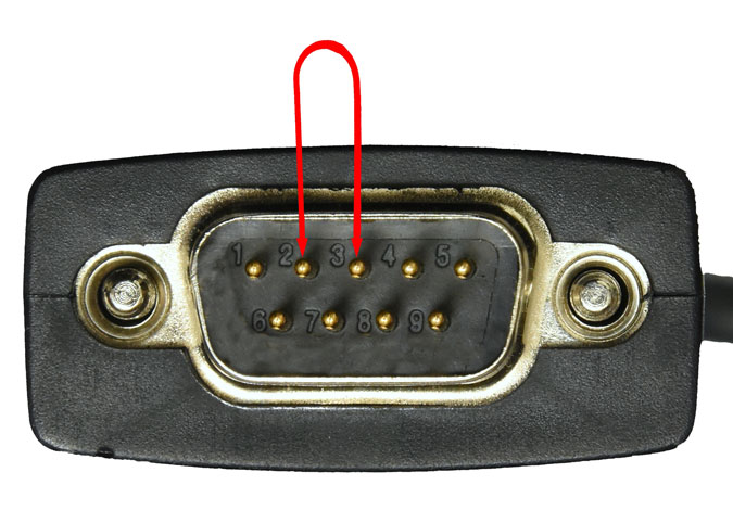
If the error persists disconnect the Data link cable from the PC serial port and temporarily short the serial port connector pins 2 & 3 together with a metal screw driver blade or piece of wire.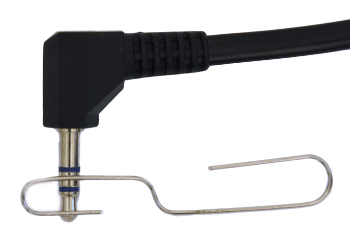
If error message popup box changes to “Short circuit detected in data link”, then the most likely cause is a faulty data link cable. If the error persists then the wrong com port number has been selected, or the selected Serial communication port is faulty or has been incorrectly installed.
If shorting the 3.5mm cable connector middle and tip contacts together produced a “Short circuit detected in data link” message add an additional short circuit to the body of the connector (ie: simultaneously short all 3 contacts of the 3.5mm plug together). If this does not cause the message to revert back to “Cannot find an ECU. Check data link” then the Ground wire of the data link cable is broken.
4.2 COMMUNICATION LINK IS SHORT CIRCUITED
For the “Short circuit detected in data link” error popup window perform the following test:
Disconnect the 3.5mm Data link cable connector from the ECU. If error message popup box changes to “Cannot find an ECU. Check data link”, then the ECU or its Serial communication socket is most likely at fault. If the error persists disconnect the Data link cable from the PC serial port. If error message popup box changes to “Cannot find an ECU. Check data link” then the most likely cause is a faulty data link cable. If the error persists then the Serial communication port is faulty or has been configured in loopback mode (i.e.: internally returns any data output)
Notes:
- If a USB to Serial adaptor is used, connect the adaptor to the same USB port for every use. This will ensure that the COM number remains unchanged, avoiding the need to adjust the port advanced settings or reconfigure the Autronic software to use the new COM number.
- Do not make the serial connection between the PC and a powered ECU before the PC has finished its boot-up process. Many PC operating systems (including Windows versions starting with XP and NT) will interpret the data stream output from Autronic ECUs as being from a serial pointing device (i.e .: mouse). The PC serial communications port is then automatically configured for mouse use and will become unavailable for PC to ECU communication. Disconnect or power down the ECU, and then restart the PC to restore normal serial communication port functionality.
LAMBDA MEASUREMENT
FAQ : WILL MY AUTRONIC LAMBDA METER WORK WITH A UEGO SENSOR
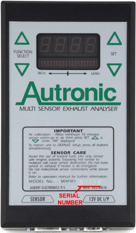
Autronic MAFM1 Lambda meters have been marketed as ‘A’ & ‘B’ variants. Both variants are compatible with the Bosch LSM11 (4-wire) O2 sensor. The ‘B’ variant is also compatible with the UEGO sensor supplied by Autronic. If a UEGO sensor is connected to an ‘A’ variant meter, it will continuously display ‘SENSOR FAULTY’. No damage to the sensor or meter will occur, provided that they are connected together using a standard Autronic ‘UEGO’ sensor harness.
Refer to the LSM11 tab on the LAMBDA SENSORS page for current LSM11 usage recommendations
Meter variant can be determined from the serial number on the front decal. The character between ‘MAFM1’ and the 4 digit serial number will be either ‘A’ or ‘B’ (see image).
The variant can also be determined by scrolling through the available functions of a powered meter using the left side ‘FUNCTION SELECT’ buttons. ‘A’ variants allow scrolling from 0 to 10 while ‘B’ variants allow 0 to 14.
For “A” version meters, we offer a cost effective upgrade service for the conversion to “B” version specification, that will allow the use of a UEGO sensor type. The upgrade can only be performed on meters that are in good condition. Prior to work commencement, internal inspection of the meter to confirm the circuit board assembly’s suitability for upgrade is required. This upgrade does not affect the meter’s compatibility with the LSM11 sensor
FAQ: DIAGNOSING A WATER DAMAGED LAMBDA SENSOR
Lambda sensors are intolerant to thermal shock. Immediate destruction will result if the sensor tip is exposed to water or liquid fuel (especially alcohol) while the sensor is powered and/or hot. Sensor failure is a common occurrence when the sensor is installed into an exhaust system tail pipe, and power is applied to the meter before the exhaust system is fully warm and condensate free.
When hit by a liquid the sensor’s ceramic element is usually shattered. Sensors with this damage, cause a ‘SENSOR FAULTY’ message to be repeatedly displayed once the meter judges the sensor to be fully warmed.
This condition can usually be confirmed be shaking the cooled sensor while holding it in such a manner to prevent the sealing washer rattling. In a quiet environment a rattle will be heard from the shattered sensor element.
DIRECT FIRE CAPACITOR DISCHARGE IGNITION
FAQ: DFCDI – COIL COMPATIBILITY
Many users enquire about the compatibility of Autronic Capacitor Discharge Ignitions and Original Equipment Manufacturer (OEM) ignition coils. Use of these OEM coils is convenient and physically neat, especially when Coil on Plug (COP) coils are used. In many applications these coils are suitable. Coils with inbuilt igniters or with an internal electrical connection between the primary (low voltage) winding and ground are unsuitable and MUST NOT BE USED. Some OEM coils are unable to withstand the additional stress imposed by high power capacitor discharge ignition and may have a high incidence of failure. Failure due to internal insulation breakdown can be minimized by NOT operating the Ignition when the coil is disconnected from its spark plug.
These OEM coils when connected singly to a single CD ignition, generally perform satisfactorily for moderately boosted forced induction engines. For heavily boosted engines a coil specifically designed for use in capacitor discharge ignition systems will generally provide superior performance.
When connecting 2 coils (OEM or Aftermarket) to a single CD ignition output for waste spark applications, the coils electrical properties determine their suitability and if suitable, the correct method of connection. Incorrect connection will cause spark energy to be diverted away from the cylinder on its compression stroke, resulting in engine misfire under heavy load operation. The electrical property “mutual inductance”, a measure of the electrical coupling between the coils’ primary and secondary windings is the determining property. Low mutual inductance coils have tightly coupled windings and are only suitable for series electrical connection. High mutual inductance coils have loosely coupled windings and are only suitable for parallel electrical connection. Coils with intermediate mutual inductance have moderately coupled windings and are unsuitable for either series or parallel electrical connection and should not be used. See the Autronic wiring diagrams for the relevant series and parallel connection method that suits your coils. If uncertain of the characteristics of your coils, it is recommended that each pair be replaced with a doubled ended coil specifically designed for use in capacitor discharge ignition systems.