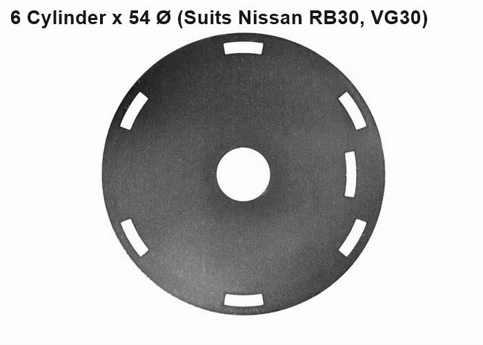
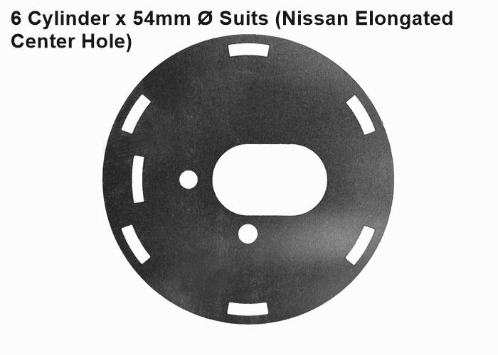
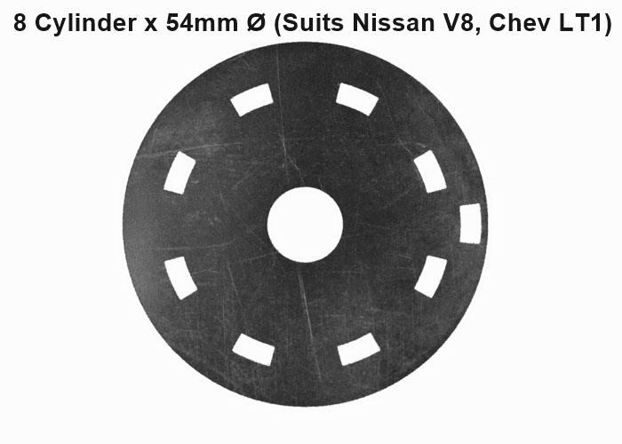
OPTICAL TRIGGER
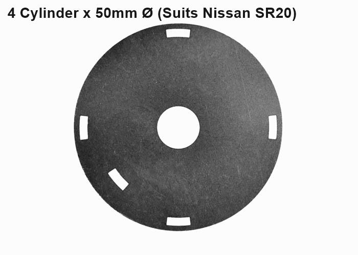
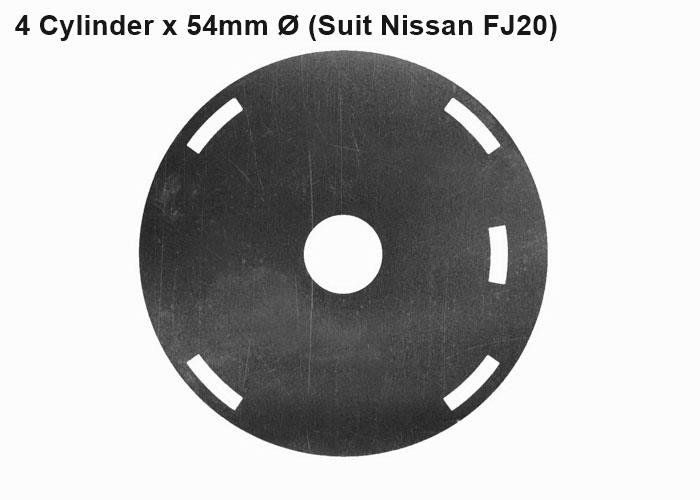
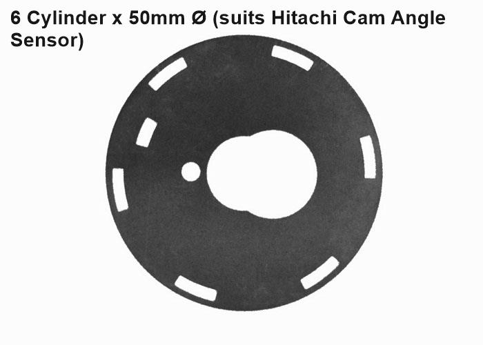
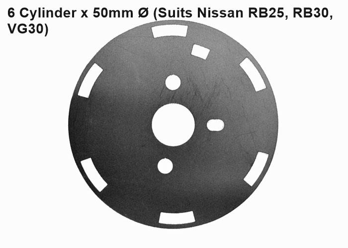
A range of precision laser cut stainless steel disks for the most common Optical Distributor and Cam Angle Sensor (CAS) units. Used to convert the output signal trigger waveform from fine pitch pattern (360 pulses per rev) to a simple trigger pattern. Available for Nissan and Chevrolet Optical Distributor and Cam Angle Sensor (CAS) units. Use with Engine Management ECUs that are incompatible with fine pitch triggers. SMC, SM2 and early revision SM4 Engine Management ECUs require this trigger conversion.
Description
A range of precision laser cut stainless steel disks for the most common Optical Distributor and Cam Angle Sensor (CAS) units. Used to convert the output signal trigger waveform from fine pitch pattern (360 pulses per rev) to a simple trigger pattern. Available for Nissan and Chevrolet Optical Distributor and Cam Angle Sensor (CAS) units. Use with Engine Management ECUs that are incompatible with fine pitch triggers. SMC, SM2 and early revision SM4 Engine Management ECUs require this trigger conversion.
Application Info
-
Correct operation of Optical Distributor or Cam Angle Sensor (CAS) unit (as applicable) requires the
opto-electronic module to be in excellent condition. Old opto-electronic modules that have degraded light
sources and light sensors, will not function correctly with any of these disks. Also we have observed poor
results with aftermarket (non OEM) opto-electronic modules. We recommend that these disks only be used with used
new or near new OEM opto-electronic modules. -
Excessive backlash in the Optical Distributor or Cam Angle Sensor (CAS) drive will cause erratic and/or
erroneous triggering. Check for, and correct any excessive drive wear before using any of these disks. -
When installing the disk, pay careful attention to the correct positioning of alignment holes and pegs (if
applicable).Disks without any location keying should be installed and aligned using the following procedure:
Install the Optical Distributor or Cam Angle Sensor (CAS) unit (as applicble) on to the engine.
Lock it in position at the middle of its adjustment range. Rotate engine crankshaft in foward direction until it
is at the appropriate trigger position (usually 60 deg before TDC (compression stroke) for No1. cylinder).
Install the trigger disk so that the single slot for the inner sensor has just completely passed the sensor
centre.
Rotate the disk further foward until next outer slot edge is coincident with the sensor centre.
Lock the disk in place. Set the Engine management ECU for the correct trigger edge polarities for both the
Cylinder and Sync pulses.
Once engine is running, trim actual ignition timing to match ECU commanded setting by carefully rotating the
Optical Distributor or Cam angle sensor (CAS) unit (as applicble)
Purchase options