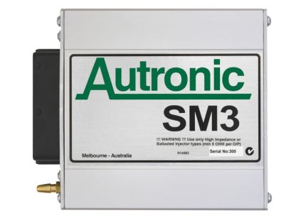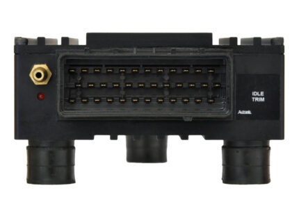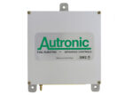
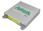
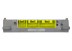

SM2 ECU
The Autronic SM2 Sequential Engine Management System offers versatile engine management for engine performance upgrades. It caters for the requirements of virtually any spark ignition port injected engine that is not equipped with either drive-by-wire throttle or feedback controlled variable camshafts.
Description
- High output supercharged or turbocharged engines, with either multi point and/or center point injection
- Rotary (2 rotor) and two stroke engines
-
Engines having uneven firing sequences such as 2 and 4 cylinder “V” configuration motor cycle engines
and V6 motor vehicle engines
A user friendly Windows software program provides the means of interrogating this engine management system enabling speedy diagnosis and calibration. This program, in combination with intelligence in the management system, allows the user to select the finest calibration detail required to match the application, in minimum time. Calibration sophistication can be tailored to each application.
- ‘Full Sequential’ injection for 2 to 8 cylinder engines
- In-built Manifold Absolute pressure sensor (options to 450kPa)
- Eight Injector outputs (low or high current drive)
- Four Ignition outputs
- 3D Fuel and Ignition maps
- Engine calibration tables have up to 32 RPM x 16 Load Sites (= 512 adjustment points) that can be arbitrarily placed by the user
- Seven Auxiliary outputs in addition to fuel pump control
- Auxiliary outputs can be defined for boost control, nitrous oxide, staged injectors, camshaft timing (2 position), A/C, fan control, idle valve etc…
- Traction Control option available
- Flat Shift option available
- Launch Control option available
- Anti-Lag option available
- “Autotune” option available
- Data Logging & Error diagnostics
- Compatible with various Dash / Data loggers
LEGACY PRODUCT NOTIFICATION
This 1st generation engine management system SM2 is now designated as a legacy product. It is not recommended for new designs, instead please consider using our later generation products, such as SM3 or SM4. This product is still available to customers such as those wishing to maintain or replicate existing installations. NEW SM2 ECUs can still be purchased to match the specifications of almost any of the product’s variants. HISTORIC RACE CARS can be maintained with new replacement components that exactly match the specifications of those originally used. Autronic will continue to offer upgrade, modification and repair services for SM2. Its P.C. calibration software continues to be updated with calibration support for recently released injectors.
!!!! IMPORTANT !!!!
In many markets, fitting this product to public road going emission controlled vehicles is illegal. Contact the relevant local authorities to determine the technical and legal requirements of your proposed modification prior to installation.
WARNING: AUTRONIC SM2 ECUs do not provide the level of redundancy required for failsafe engine operation in manned aircraft. USE FOR ENGINE CONTROL IN MANNED AIRCRAFT IS NOT PERMITTED!!!
SPECIFICATIONS
IMPORTANT: Please note that this product is intended for high performance motor sport applications and compliance with statutory regulations when used on public roads cannot be guaranteed.
Features.
- Eight injector drivers for full sequential operation on engines up to eight cylinders. Staging injection possible in some applications. May be set for ‘semi-sequential’ operation on engines that have more than 8 cylinders (e.g. 12 cylinder engine using 6 groups of two cylinders). All common port injector types catered for (0.9 ohm to 16 ohm coil resistance) with selectable Low or High current driver. When ordering, request an initial configuration to suit injectors. Drive current selection is field re-configurable.
-
Four open collector outputs for triggering Capacitor Discharge or Smart Inductive Ignition Modules.
Note: Standard product does NOT provide dwell control (installation of optional dwell control interface module/s is required).
- Single coil distributor, twin coil distributor or multicoil distributor-less ignition configurations are possible on most engines.
- Fuel pump safety shut-off. Pump stops 3 to 4 seconds after the engine stops.
- Seven auxiliary outputs in addition to fuel pump control. Auxiliary outputs can be defined for boost control, nitrous oxide, staged injectors, camshaft timing, A/C, fan control, idle valve etc…
- User choice of Manifold absolute pressure or Throttle position as Engine load input. Internal absolute pressure sensor for simplified installation 0 to 200 kPa (0 to 29.4 PSI) and 0 to 300 kPa (0 to 44.1 PSI) available from stock. 0 to 450 kPa (0 to 66.1 PSI) available on request.
- Autronic ‘Mass-flow determination method’ simplifies fuel delivery calibration, especially for multi-butterfly or variable inlet geometry engines equipped with forced induction. This method, combined with other measures, ensures precise fuel delivery matching, irrespective of altitude and exhaust back-pressure (when a back pressure sensor is connected) whilst reducing calibration effort.
- Compensation of engine control parameters for engine operation over a wide altitude range (fuel delivery, ignition timing and boost pressure).
- Measurement of and correction for exhaust back pressure.
- Unique transient calibration strategy allows accurate control of fuel delivery under both acceleration and deceleration.
- Direct connect a narrow band O2 sensor for closed loop emissions control, or a compatible wide band Air-fuel ratio meter (e.g. Autronic MAFM1) for full range engine tuning.
- Autronic ‘Autotune’ self-tune software feature for air-fuel ratio calibration requiring minimal user intervention (compatible with firmware versions from v1.90).
- Closed loop (feedback) boost pressure control for turbocharged engines with multiple calibration curves selectable by switch input and/or gear ratio (e.g. lower boost curve for use in low gear).
- Closed loop (feedback) idle speed control.
- Adaptive learning (with memory) to minimize the number of user setups required and to provide optimal control of air/fuel ratio, boost pressure and idle stability.
- Precise compensation for injector dead-time and non-linearity. Large library of predefined compensations for popular injector types.
- Precise spark advance control strategy for both static and dynamic operating conditions.
- User selectable spark and fuel delivery strategy for abnormal engine operation conditions to minimize possibility of engine damage whilst still maintaining engine operation (e.g. over heated or over boosted).
- Comprehensive limp-home functions with user selectable default settings that, whenever possible, ensure engine operation can continue after sensor failure has occurred.
- Coolant temperature dependent Rev Limiter with soft characteristic that uses a combination of fuel delivery and spark control.
- Traction Control, Flat Shift, Launch Control & Anti-Lag (Turbo boost enhancement) are available (depending on Firmware version fitted).
- Diagnostic/Error indicator light with memory for reporting sensor or ECU fault conditions. Ideal for detection of intermittent fault conditions. Error history information is also accessible from P.C. screen.
- User configurable internal data logging of up to 17 channels with the selected channels being sampled as fast as 50 times a second. 32k bytes of non-volatile memory. Peak capture feature aids detection of over-rev, over-boost and over-temperature conditions.
- Serial data port can be used in a bi-directional communication mode for P.C. calibration, monitoring and data logging, or in unidirectional mode for data streaming output to a Dash / Data logger. Remote adjustment and/or monitoring are possible if Radio modems are added to the serial link.
- Simultaneous and independent operation of the internal data logger and serial port data link is allowed.
- Control of engine cooling fans and coordination with air conditioner operation.
- Control of Water Injection/spray or Intercooler fan/s cooling function for intake charge temperature reduction in Turbo/super charged applications.
- Programmable On-Off output function for solenoid or relay driving that operates according to engine speed and load (e.g. can be used for gear shift control or light, over rev indicator, inlet camshaft timing selection or control of a supplementary electric fuel pump that augments main fuel pump).
- Programmable proportional output function that can be used for additional functions, or as an extra on/off output.
- Fuel used pulse output to electronic or electromechanical counter with resolution of 0.1 litres (or use with trip computer).
- Compatible with optional No.1 cylinder spark plug pick-up interface unit that allows sequential injector operation on engines equipped with distributor ignition, without the need for separate crank/camshaft sensors or a special multi-sensor distributor.
Note: The above list describes the product family capability. Individual product feature set depends upon firmware version fitted. See ‘SM2 ECU FIRMWARE VERSION – FEATURE MATRIX’ document.
Interface Requirements.
INPUTS
Sensors:
- Crankshaft position input. Hall Effect pickup (use optional Reluctor interface for compatibility with magnetic reluctor type pickups)
- No.1 cylinder reference. Hall Effect pickup (use optional Reluctor interface for compatibility with magnetic reluctor type pickups)
- Road speed input. Hall Effect pickup (use optional Reluctor interface for compatibility with magnetic reluctor type pickups)
- Additional Road speed or Turbo speed input. Hall Effect pickup (use optional Reluctor interface for compatibility with magnetic reluctor type pickups).
- Manifold pressure (Internal to ECU)
- Barometric pressure derived from Manifold pressure sensor
- Throttle position
- Intake air temperature
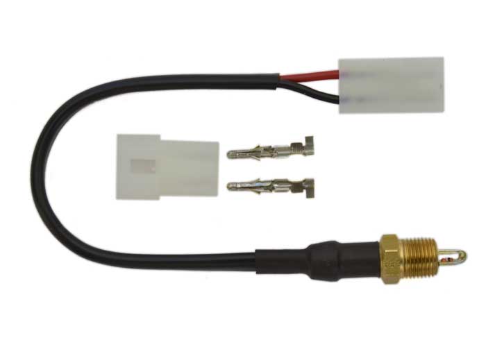
- Engine coolant temperature
- Exhaust back pressure (optional)
- Exhaust oxygen sensor (or optional Air/Fuel Ratio meter for wide band measurement)
Switches:
- Air conditioner request (Switch to Gnd)
- Boost curve select (Switch to Gnd)
- Bi-directional I/O (Switch to Gnd. Requires pull-up to +5 V)
Overall / Idle mixture adjustor. (Configurable, internal to ECU and screwdriver adjustable from outside)
OUTPUTS
8 x injector drivers:
User selectable 4A/1A or 2A/0.5A Peak/Hold switching type
(Note: Early SM2 production. ECUs were fitted with fixed current peak/hold drivers. These variants can only have injector driver current rating changed by performing complete driver replacement. The AUTRONIC service facility can perform this service, subject to drive availability)
4 x ignition outputs:
Each are open collector output type compatible with:
- ‘Smart’ Inductive high energy ignitions that have internal dwell control
- Autronic Capacitor Discharge Ignitions
- Other capacitor discharge ignitions e.g. MSD 6A etc…
(Note: The SM2 ECU is primarily intended for extreme performance applications and is best suited for use with capacitor discharge ignitions. Optional dwell interface module/s can be installed that will provide compatibility with non-dwell controlled inductive high energy ignition systems)
Fuel Pump:
Auxiliary
4 x On-Off O/Ps (comprising 2 x 1A Open collector & 1 x 1A High side) suitable for:
- Air conditioner clutch relay control
- Engine/Air conditioner condenser cooling fan relay control
- Engine cooling fan relay control
- Spare On-Off output with user define characteristic
- Fuel used pulse output (for trip computer function)2 x Proportional variable O/Ps (comprising 2 x 1A High side Duty cycle & 1 x 0 to 1A DC current sink) suitable for:
- Idle speed actuator (variable duty cycle or current driven types)
- Turbocharger waste gate control duty cycle valve (suits Autronic low & large high capacity & most OEM types)
- Spare variable output with user define characteristic
SERIAL I/O
RS232 communication port for connection to P.C., Dash or Data logger
SOFTWARE COMPATIBILITY
-
SM2 firmware versions v1.34 to v2.07
Software available for P.C.s running Win XP, Vista, Win7 & Win8 32 & 64 bit (requires x86-32bit code support), & MS-DOS
-
Early SM2 to firmware versions to v1.07
Software only available for P.C.s running MS-DOS only (Recommend ECU firmware update to >= v1.34)
|
Microcomputer |
. |
Intel |
|
Supply Voltage |
Normal |
6.2V |
|
Current |
@ @ |
< 1 < 1 Amp |
|
Outputs |
Injector |
8 |
|
Ignition |
4 |
|
|
On-Off |
4 x Open collector |
|
|
PWM |
2 x High side 1A |
|
|
Linear |
1 x Variable |
|
|
Inputs |
Digital |
1 x Crankshaft 1 x Camshaft 1 x Vehicle Speed 1 x Turbo or |
|
Switch |
2 x Switch to Gnd 1 x Switch to Gnd |
|
|
Analog |
1 x Throttle 1 x Manifold Air 1 x Engine Coolant 1 x O2 Sensor or 1 x Exhaust Back 4 x Temperature |
|
|
Serial |
1 x RS232 |
|
|
Operating |
Min |
– 40 deg C |
|
Engine |
Number |
1, 2, 3, 4, 5, 6, |
|
Engine RPM Range |
0 |
Engines up to 4 |
|
Injection |
Min |
0.7 msec. |
|
Injection Timing |
Range |
0 to 720 deg (crank |
|
Ignition Timing |
Advance |
0 to 45 deg (crank |
|
Fuel |
No. |
16 (max) both Load |
|
Size |
L |
190 * 190 * 38 mm |
|
Weight |
. |
1.35 |
|
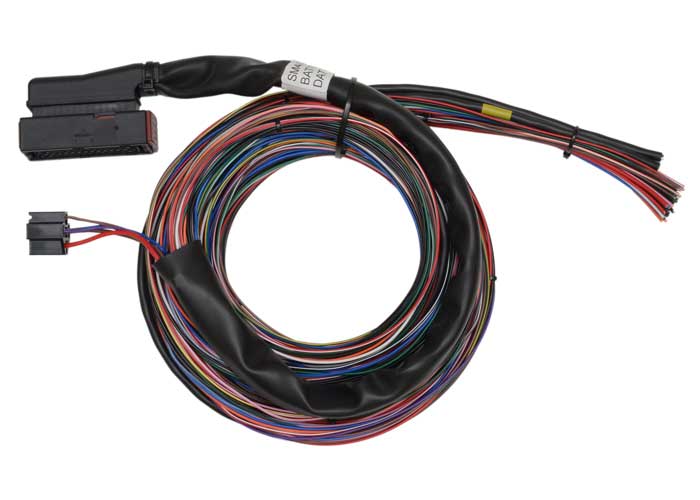
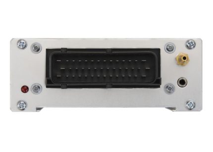
External Connectors |
52 socket |
10 way high current |
|
Serial |
3.5mm |
Application Info
Purchase options