Hot


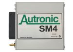
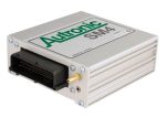
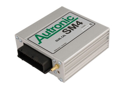
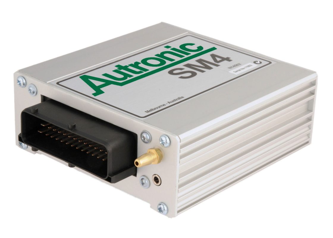
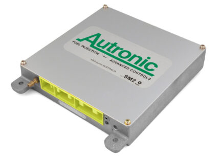
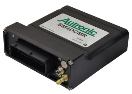
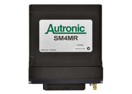
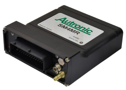
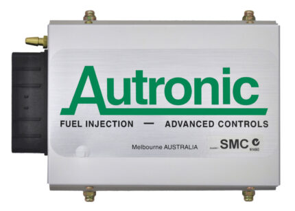
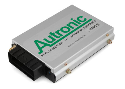
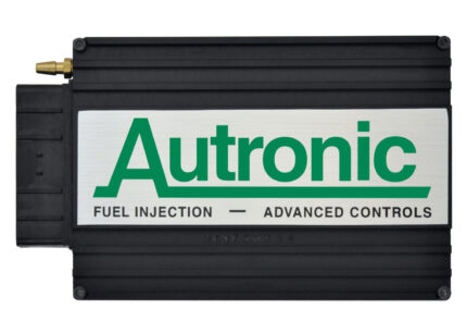
SM4 ECU
The SM4 is our highly configurable 3rd generation 8 Injector output / 4 Ignition output Engine Management ECU. Its numerous features provide an enhanced road car driving experience, exhaust emission control and suitability for motorsport use.
Description
•The ECUs rich feature set allows it to support a wide variety of engine types including most reciprocating engines that have between 1 to 16 cylinders, and 2 rotor Rotary engines. Feedback control of 2 variable camshafts is possible.
•Many engine related standard control functions are provided. An additional ten general purpose control functions are suited to engine or vehicle related control. Four of these control functions are highly capable PID (proportional, integral, differential) feedback controllers.
•A comprehensive calibration scheme offers precise adaption of fuel injection and ignition angle to the needs of your engine over wide RPM and load ranges.
•A sophisticated transient fuelling scheme enhances air/fuel ratio control accuracy under dynamic conditions producing measurable performance gains over previous generation products.
•Improved start-up fuelling strategy assists with rapid engine starts, especially at low temperatures.
•PC software with “Autotune” feature assists with rapid fuel delivery calibration.
•Capable of individual cylinder knock control when fitted with a compatible Autronic Knock control processor.
A high level of protection from interference and tolerance of trigger input errors has been built into this ECU ensuring a smooth running engine even under extremely difficult conditions.
•High efficiency switching type injector drivers and power supply circuitry ensures low power consumption and cool running for reliable operation in hot environments.
•Calibration selection by switch is possible with SM4 Dual calibration version.
See “SM4DC Dual Calibration”
•Also available with Black Anodized Aluminium O-ring sealed billet case for marine and other arduous applications.
See “SM4MR Marine ECU”
!!!! IMPORTANT !!!!
In many markets, fitting this product to public road going emission controlled vehicles is illegal. Contact the relevant local authorities to determine the technical and legal requirements of your proposed modification prior to installation.
WARNING: AUTRONIC SM4 ECUs do not provide the level of redundancy required for failsafe engine operation in manned aircraft. USE FOR ENGINE CONTROL IN MANNED AIRCRAFT IS NOT PERMITTED!!!
SPECIFICATIONS
AUTRONIC SM4 ECU Specifications
|
Microcomputer |
|
Intel |
|
Power |
Normal operation Operational limits
Survival limits |
12v to 15v DC 6.2v to 18v DC +/- 23v (5 minutes) Outside +/-23 volt
100A (Inductive surge <1mSEC) -10A (Inductive surge <100uSEC) |
|
Power |
Off ECU only At Idle At maximum Load |
< 1mA < 0.2 A < 1.0 A < 16 A (depending on |
|
Operating temperature |
Limits |
-40°C to +85°C |
|
Storage temperature |
Limits |
-40°C to +105°C |
|
Engine |
Number of cylinders Types |
1, 2 |
|
Engine |
1 to 4 cylinders 5 or 6 cylinders 7 or 8 cylinders 10 to 16 cylinders |
0 0 0 0 |
|
Hardware |
Injectors
Ignition GP Outputs
|
8 4 4 4 2 |
|
Injection |
Minimum output pulse time Maximum output pulse time Resolution Accuracy |
0.65 50 0.1% < |
|
Injection |
4 stroke Range 2 stroke / Rotary Range Resolution Accuracy |
0 0 2.8° < |
|
Ignition |
Timing modes Timing range Resolution Accuracy |
Dwell -64° 0.5° 0.3° |
|
Base |
RPM sites Load sites |
1 1 |
|
Data |
Size |
507 |
|
Housing |
L * W * H Type |
130 Anodized |
|
Weight |
|
0.5 |
|
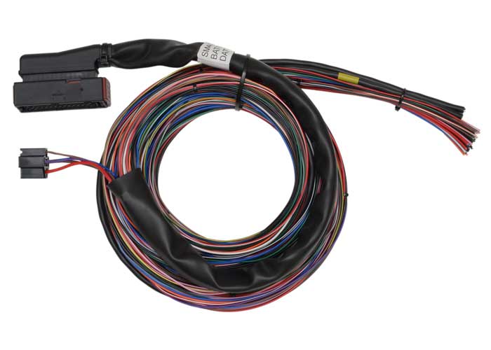
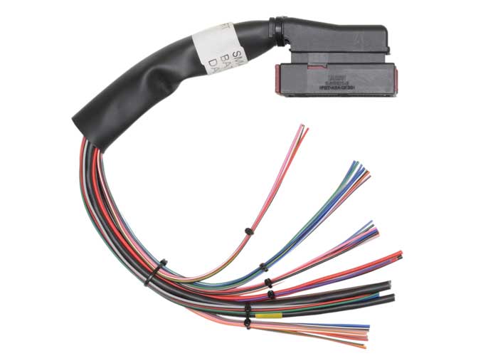
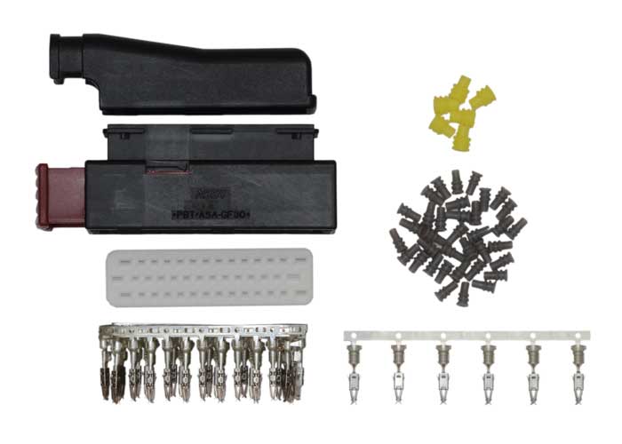
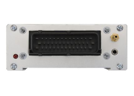
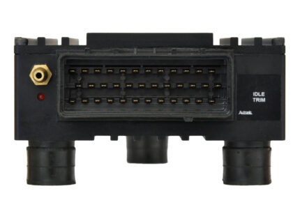
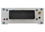
Connectors |
Main connector Communications |
42 3.5 |
Notes: 1 2 stroke: 1 to 4 cylinders 0 to 15000 RPM, 5 or 6 cylinders 0 to 12000 RPM, 7 or 8 cylinders 0 to 10000 RPM, 10 to 12 cylinders 0 to 8000 RPM.
2 A high current injector drive version is available on special order. Each group is selectable 8A/2A or 4A/1A (Peak/Hold). Maximum supply current < 20A.
Application Info
Purchase options